As an important category of internal combustion engine, the working efficiency of its cooling system directly affects the key performance of the engine such as thermal efficiency, emission and fuel consumption. The main components of the engine forced cooling system include water pump, fan, radiator, thermostat, cooling water jacket and circulation pipeline. Its main function is to maintain the working temperature of each part of the engine within a reasonable range. The engine thermostat can change the circulation path and flow rate of the coolant according to the temperature change of the coolant, so as to ensure that all parts of the engine are maintained within the appropriate temperature range.
Limited by the development and application cost of new thermostats, the thermostats of most automobile engines are still mechanical wax thermostats. The application of new technologies such as split cooling, integrated exhaust manifolds and electronic water pumps can Meet the cooling performance requirements of most automobiles. However, with the development of engine electronic electrification, some higher-end engines have begun to gradually apply electronic automotive thermostat to meet higher performance and emission requirements. The development and application costs of electronic thermostats are relatively high, the technology is not yet fully mature, and it will take time for large-scale promotion and application.
Since the development of practical thermostat technology in the 1930s, the basic principle and structure of mechanical thermostats have not changed much. Among them, the most mature and widely used mechanical thermostat is the wax thermostat. device. Wax Thermostat
It is mainly composed of main valve, auxiliary valve, induction body (wax bag), push rod, bracket, spring, etc. As the core part of the thermostat, the induction body is generally divided into three types: hose type, plunger type and diaphragm type. Among them, the hose type induction body is the most widely used. The basic structure of the wax type thermostat is shown in Figure 1. Show.
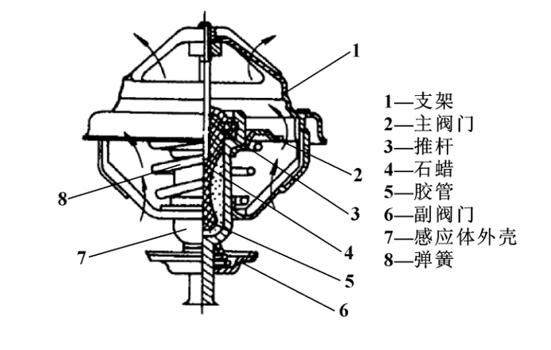
Figure 1 Wax Thermostat
During the engine ignition and warm-up process, the coolant temperature is low, the paraffin in the induction body is solid, the auxiliary valve is opened, the main valve is closed, and the coolant flows inside the engine under the action of the water pump without passing through the radiator, which is beneficial to the comparison Warm up the machine quickly, which is called a small cycle at this time; as the temperature of the coolant increases, after reaching the initial opening temperature of the thermostat, the paraffin in the induction body undergoes a phase change, gradually transforming into a solid-liquid mixed state, and the paraffin expands. As a result, the push rod in the hose is squeezed. Under the reaction force of the push rod, the main valve is gradually opened, and the auxiliary valve is gradually closed. The valve enters the radiator, and after the radiator is cooled, it flows back into the engine to avoid the rapid rise of the coolant temperature. At this time, it is called a mixed cycle; when the coolant temperature rises to the fully open temperature of the thermostat, the main The valve is fully opened and the auxiliary valve is closed. At this time, the coolant circulating in the engine will all flow through the radiator under the action of the water pump, and the coolant will be forcedly cooled under the action of the fan and the radiator, which is called a large circulation. The optimal working temperature of the engine is in an interval, neither the lower the better nor the higher the better, and the coolant path and flow distribution under different working conditions can be realized through the thermostat to control the engine working temperature. the goal of. Due to the simple structure and low cost of the wax thermostat, most automobile engines on the market currently use the wax thermostat. During the working process of the engine, the different thermal load states of the cylinder block and the cylinder head will cause the heating rate of the cylinder head to be higher than the heating rate of the cylinder block. Optimum operating temperature requirements. With the upgrading of engine technology, an engine split-flow cooling technology using dual thermostats has emerged. quantity coefficient, reducing friction.
Arranging only one thermostat cannot meet the optimal working temperature requirements of different parts of the engine. With the upgrading of engine technology, an engine split-flow cooling technology using dual thermostats has emerged. quantity coefficient, reducing friction.
The composition of double thermostats is generally divided into two types: one is that the double thermostats are integrated and installed on the engine as one part, and the other is that the two thermostats are installed as two independent parts in different parts of the engine. Location. Figure 2 is a schematic diagram of a dual thermostat assembly. The dual thermostat includes two thermostats with different initial opening temperatures, which control the coolant flow paths of the cylinder body water jacket and the cylinder head water jacket respectively. Schematic diagram of the car cooling system parts. When the engine starts, the coolant temperature is low, the thermostat 1 and thermostat 2 are both closed, the coolant flows out through the water pump into the water jacket of the cylinder head, part of the outflow coolant returns to the cylinder head, and the other part of the coolant flows back to the cylinder head. Flow to the heater core, the coolant in the cylinder block water jacket does not flow; after a period of time, as the coolant temperature rises, the thermostat 1 valve starts to open, the thermostat 2 is still closed, and flows out from the cylinder head at this time Part of the high-temperature coolant flows to the radiator and heater core, and part of the coolant returns to the cylinder head; as the coolant temperature further increases, the valves of thermostat 1 and thermostat 2 are both opened, and the The high-temperature coolant starts to flow, collects with the high-temperature coolant of the cylinder head, and finally flows to the radiator and other circuits. Compared with the traditional single thermostat arrangement, the engine based on the double thermostat design can realize the split cooling of the cylinder block and cylinder head, which can speed up the warm-up speed, reduce the friction, reduce the heat transfer of the engine to the cylinder wall, and improve the cylinder head at the same time. Intake and exhaust efficiency.
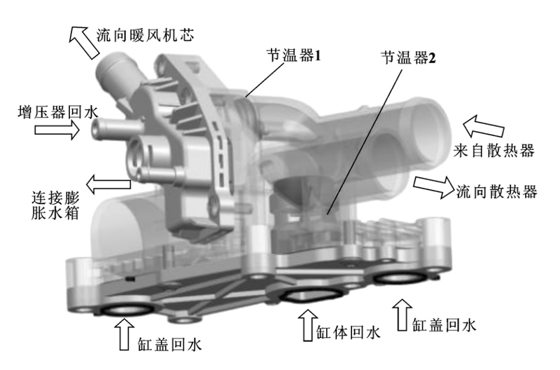
Figure 2 Double Thermostat Assembly
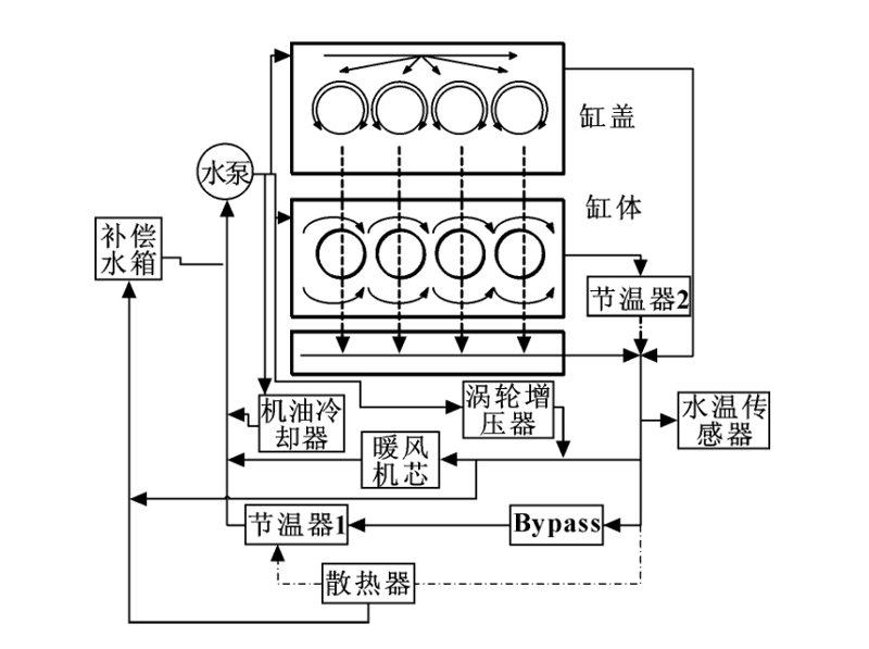
Figure 3 Schematic Of Split Cooling System
Limited by the working principle of the wax thermostat, when the paraffin is heated and expands to drive the valve to act, there are problems of response delay and valve "hysteresis", and it is impossible to accurately control the coolant temperature. Therefore, relevant researchers have improved the material and structure of the wax thermostat, such as finding the type of temperature-sensing medium to replace paraffin, and improving the structure of the valve drive unit.
Liu Peng et al. designed a pneumatic thermostat that uses acetone as a temperature sensing medium, and its main structure is shown in Figure 4. The research results show that, compared with the wax thermostat, the pneumatic thermostat has the advantages of fast response, simple structure and long service life. This study is an innovative exploration of the improvement of the mechanical thermostat, but it has not been verified on the engine bench and the whole vehicle. Chen Zhiheng et al. proposed a new type of thermostat structure with cylindrical coil spring copper-based memory alloy as the driving unit through the transformation of the wax thermostat. As shown in Figure 5, the shape memory alloy coil spring compresses or extends when the coolant temperature changes, driving the main and auxiliary valves to act, replacing the traditional paraffin induction body. The research shows that the use of shape memory alloy as the thermostat of the valve drive unit has the advantages of sensitive response and simple structure. Since the research is carried out under the structure of the traditional wax thermostat, the overall structure needs to be further improved to meet the durability requirements of the engine under extreme working conditions. S K KIM et al. added 10% to 20% graphene and paraffin in the wax thermostat, and systematically studied the effect of graphene content on the response time and melting temperature of the wax thermostat. The test results showed that adding graphite The olefinic thermostat can shorten the response time and improve the thermostat "hysteresis" problem.
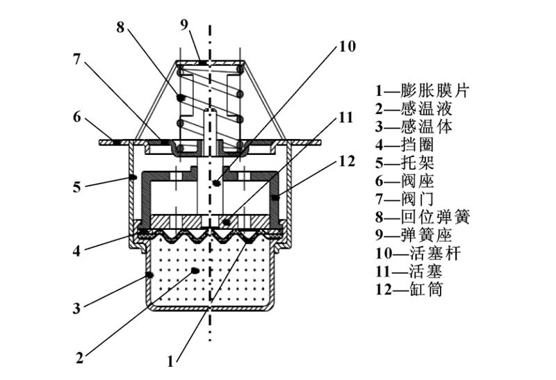
Figure 4 Pneumatic Thermostat
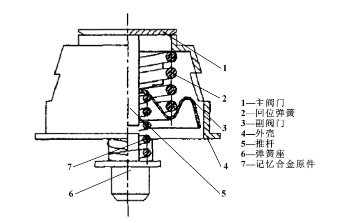
Figure 5 Shape Memory Alloy Thermostat
The working process of the traditional mechanical thermostat is "passively" regulated by the temperature of the coolant, and there is a problem of response lag. With the development of engine electrification, an electronic thermostat that can actively adjust the temperature is gradually applied. in the engine cooling system. At present, there are two main types of electronic thermostat applications: electric heating wax thermostat and map controlled thermostats.
As shown in Figure 6, the optimal operating temperature required by the engine under different load conditions is often opposite: at low load (such as driving at a constant speed on a flat ground), a higher coolant temperature can keep the oil temperature at a higher temperature. High level, reduce oil viscosity, reduce friction loss of moving structure, save fuel consumption, while higher working temperature also means lower pollutant emission value; in high load (such as climbing, accelerating), in order to obtain maximum Power needs to increase the intake air volume, and at this time, it is necessary to strengthen the cooling and reduce the coolant temperature. Figure 7 shows the schematic diagram of the basic structure of the electronically controlled wax type thermostat. Compared with the traditional wax type thermostat, the electronically controlled wax type thermostat has a heating resistance added to the push rod, and its initial opening temperature is higher than that of the traditional wax type thermostat. The traditional wax thermostat has a faster response speed and a wider working temperature range. Its working process is: when the engine is under low load, there is no signal input, and the function of the thermostat is equivalent to a pure mechanical wax thermostat; When the load is high, the ECU starts to receive the PWM pulse width modulation signal, and can heat the resistance according to the MAP diagram, and the paraffin is heated and expanded, forcing the valve to open in advance or increase the opening amount.
Ma Wei et al. studied the fuel-saving potential of the electrically heated wax thermostat and conducted a CAE analysis of the thermal load of the engine. The results show that when the engine BMEP is 3 × 10⁵ MPa at a small load, the fuel consumption can be improved by increasing the coolant outlet temperature from 85 ℃ to about 105 ℃ (simulating the large-cycle closed state of the electronically controlled wax thermostat at a small load). This is around 2% lower, while fuel consumption can also be around 1% lower at moderate loads. Yang Yang et al. conducted a bench test on the Changan D18T engine. The test shows that after using the electric heating wax thermostat, the control system can control the temperature of the cooling liquid to be near the optimal cooling water temperature corresponding to each working condition, and the fuel saving effect can reach 2% to 6% under medium and small loads. The effectiveness and feasibility of the control scheme of the electronically controlled wax thermostat are presented. In order to verify the effectiveness of the electric heating wax thermostat, Zhang Liping et al conducted a bench test on a 1.5L displacement engine. The results show that the control system using the electric heating wax thermostat can control the cooling water temperature near the optimal cooling water temperature corresponding to each working condition, and the fuel saving effect can reach 0. 5% to 2. 6%. Li Jun et al. used the electric heating wax thermostat controlled by fuzzy PID, compared the fuel consumption of the vehicle with the mechanical thermostat and the electric heating wax thermostat, and found that the electronic control using fuzzy PID control under the NEDC condition The fuel-saving efficiency of the wax thermostat can reach 0.7%, and the fuel-saving efficiency can reach up to 4.7% under the steady-state working condition of low speed and small load.
Another form of electronic thermostat is to use an electronically controlled valve to replace the traditional paraffin temperature sensing valve. Compared with the traditional mechanical thermostat or electric heating wax thermostat, it has the advantages of quick response and accurate temperature control. It can implement closed-loop control according to the operating conditions of the vehicle. Volkswagen uses an electronically controlled ball valve thermostat in its third-generation EA888. Compared with mechanical thermostats, electronically controlled ball valve thermostats enable the engine to obtain low friction and high efficiency while reducing pollutant emissions. Figure 8 is a schematic diagram of the electronically controlled ball valve thermostat of the third generation EA888 1.8T engine, which mainly includes: PPS plastic housing, DC motor, worm gear, rotating ball valve, drive shaft and coolant pump. The ball valve of the electronically controlled ball valve thermostat is connected with each water pipe port through multi-stage sealing components (main sealing ring, auxiliary sealing ring, wave spring, O-ring), and ball valve 1 and ball valve 2 are linked through toothed connection. The on-off and flow rate of each water circuit cycle can be controlled under the drive of the motor. Figure 9 shows the cycle of the engine cooling system. In terms of control, the position sensor in this electronically controlled valve thermostat communicates with the ECU through the SENT protocol, controls the ball valve rotation angle, and uses PWM power to control the speed of the DC motor.
In recent years, with the development of engine electrification, the application of electronically controlled valve thermostat has been studied at home and abroad. Wang Shuai used the electric three-way valve as the execution structure of the electronic thermostat, designed its control strategy based on the fuzzy control principle, and gave the fuzzy control MAP diagram. Data such as flow and temperature verify the feasibility of the fuzzy control strategy of the electronic thermostat. Han Song established a control strategy for the engine under all working conditions through systematic research on electronic water pumps, electronic fans, electronic thermostats and electric heaters. The results show that the electronic thermostat with fuzzy control can effectively reduce the initial opening temperature of the thermostat. The fluctuation is less than 2. 2 ℃, and can quickly stabilize near the target water temperature, and the fluctuation is less than 1 ℃. Zou Yanzhong formulated the optimal coolant temperature of the motor ball valve thermostat, established the simulation model of the electronic thermostat cooling system, and studied the control strategy. Yan Shuanghe et al. studied the influence of three states on the warm-up time, fuel consumption and emissions of a ball valve thermostat without a motor, an electronic ball valve thermostat with a water temperature correction strategy, and a motor ball valve thermostat without a water temperature correction strategy. The thermostat can increase the warm-up speed by 37. 5%, and with the water temperature correction strategy, it can more accurately characterize the engine water temperature, reduce fuel consumption and emissions, and further utilize the advantages of the motor ball valve thermostat. MITCHELL et al. compared the cooling system efficiency of wax thermostat, electric two-way valve, electric three-way valve and no thermostat under warm-up conditions, and found that the electric three-way valve thermostat has the shortest warm-up time. , minimal heat loss and temperature control accuracy. MOHAMED designed an electromagnetic three-way valve thermostat, the structure of which is shown in Figure 11. The test results show that the new electronic thermostat structure can reduce the warm-up time by about 28. 5%, and can rapidly increase the oil temperature under the NEDC cycle; at the same time, the new structure can reduce the cold start by 23. 5% % of the coolant flow, and can reduce the coolant flow by 15.2% after the warm-up is completed, thereby reducing heat dissipation and reducing pollutant emissions. JEONG et al. compared the fuel economy of electronic valve thermostat and traditional wax thermostat under FTP-75 and HWFET operating conditions. The test results show that the fuel consumption can be saved by 0.37% under the FTP-75 operating condition and 0.032% under the HWFET operating condition.
